Insulation Resistance Test
What is insulation resistance?
Insulation resistance is defined as the resistance to current leakage through and over the surface of the insulation material surrounding a conductor. It is measured in Ohm`s and its value represents a very important factor to electricians working within the electrical industry.
What is insulation resistance testing?
The insulation resistance test is an electrical test which uses a certain type and level of voltage (500V d.c. for low voltage installations i.e.: 230V) to measure insulation resistance in Ohm`s.
The measured resistance indicates the condition of the insulation between two conductive parts. An infinite resistance would be the perfect result, but no insulator is perfect, so the higher the reading the better.
The table below shows the required test voltage and the minimum required resistance in accordance with BS 7671.
| Nominal Circuit Voltage | Test Voltage | Minimum Resistance |
| Between 0 V and 50 V a.c. | 250 V d.c. | 0.5 Mohm |
| Between 50 v and 500 V a.c. | 500 V d.c. | 1Mohm |
| Between 500 V and 1000 V a.c. | 1000 V d.c. | 1 Mohm |
An easy way to understand this test is to think about it as a form of pressure test. When the test voltage of 500V d.c. is applied to a regular 230V circuit, we will see if there is any leakage from one conductor to another through the insulating material.
The Insulation Resistance test sequence:
To perform the tests needed, you will need an Insulation Resistance Tester or a multifunctional tester such as the Megger 1553.
![]() Before everything, a safe isolation procedure must be carried out.
Before everything, a safe isolation procedure must be carried out.
Step 1. Select the required circuit and disconnect its live conductors from the distribution board (the earth conductor can stay)
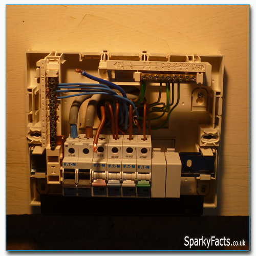
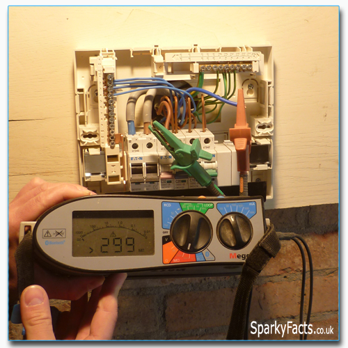
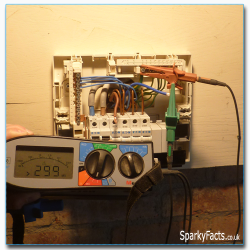
Step 2. Connect one of the test leads of the Insulation Tester to the Line conductor and the other one to the Neutral conductor. Set the tester to the required voltage and press and hold the TEST button – the tester will display a value in Ohm`s or if it is out of its range than something like this: >299 MΩ
Step 3. Repeat the test process with one of the test leads on the Line conductor and the other one on the Earth conductor
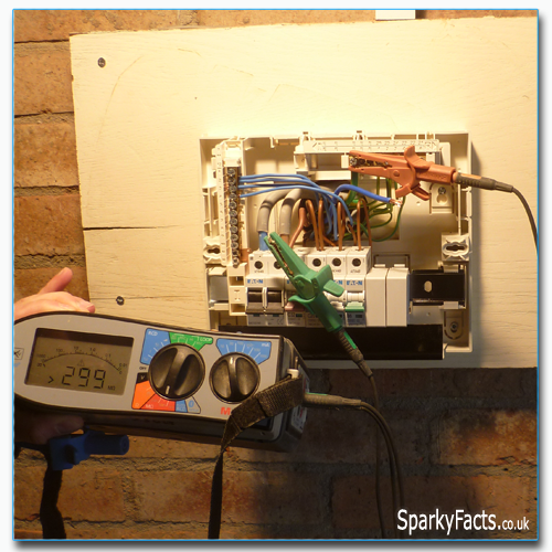
Step 4. Repeat the test process with one of the test leads on the Neutral conductor and the other one on the Earth conductor
Step 5. That is it - compare all test results to the minimum allowed value in BS7671 (1MΩ for a 230V a.c. circuit). If any of the values are lower, than further investigation is needed.
Test every circuit within the distribution board one by one, and record the test results on the Schedule of Test Results.
![]() Pro advice: You can perform this test on a whole range of circuits in a single process. You can test between all of the Line conductors and all of the Earth conductors within the distribution board. After this step, between all of the Neutral conductors and all of the Earth conductors. The only down side is that if there is a low insulation resistance reading then you will have to test the circuits one by one to find out which one has the fault on it. However, most of the time, you can save valuable time by insulation testing the entire board this way.
Pro advice: You can perform this test on a whole range of circuits in a single process. You can test between all of the Line conductors and all of the Earth conductors within the distribution board. After this step, between all of the Neutral conductors and all of the Earth conductors. The only down side is that if there is a low insulation resistance reading then you will have to test the circuits one by one to find out which one has the fault on it. However, most of the time, you can save valuable time by insulation testing the entire board this way.
The Inspection and Testing C&G 2391 practical exams
In order to verify compliance with BS 7671, you will be expected to perform insulation resistance tests on all of the circuits on the Inspection and Testing practical exam. The purpose of the tests are to verify that the insulation of conductors and electrical accessories is satisfactory and that live conductors or protective conductors are not short-circuited, or do not show a low insulation resistance.
Before testing you will be expected to check if:
-
Pilot or indicator lamps as well as other lights are disconnected
-
Voltage sensitive equipment (dimmer switches, control units etc.) are disconnected to avoid damaging them by excessive voltage.
Also before testing, the appropriate test meter and the required test voltage (500V DC; Table 61 of BS 7671) must be selected.
Next we move on to Polarity testing.
Important things to remember:
![]() These tests can be carried out all at once for every circuit (form the terminals of the main switch) or individually for every circuit to help pinpoint a fault of needed.
These tests can be carried out all at once for every circuit (form the terminals of the main switch) or individually for every circuit to help pinpoint a fault of needed.
![]() According to BS7671 readings below 1 M ohm indicate a faulty condition, everything between 1 and 2 M ohm should be investigated, and readings above 2 M ohm are satisfactory.
According to BS7671 readings below 1 M ohm indicate a faulty condition, everything between 1 and 2 M ohm should be investigated, and readings above 2 M ohm are satisfactory.
![]() During the testing remember to constantly inspect the installation for faults and signs of damages.
During the testing remember to constantly inspect the installation for faults and signs of damages.
C&G 2391 - Guide to Inspection and Testing
 Initial Verification
- Periodic Inspection and Testing
- Qualifications needed for inspection and testing
- The inspection and testing exams
- The C&G 2391 online and written exams
- The C&G 2391 practical exam - Initial Verification
- The C&G 2391 practical exam - Periodic Inspection
- Testing procedures:
- Continuity testing
- Ring circuit testing
- Insulation resistance testing
- Polarity testing
- Earth Fault Loop Impedance tests
- Prospective Fault Current test (PFC test)
- Phase sequence test
- RCD test
- Functional testing
- Certification
- Exam practice:
- C&G 2391 Unit 301 Sample Test No1
- C&G 2391 Unit 301 Sample Test No2
- C&G 2391 Unit 301 Sample Test No3
- C&G 2391 MOCK exam paper ONE with answers
- C&G 2391 EXAM QUESTIONS with answers
- Old exam papers:
- C&G 2394 - 2395 big collection of past exam papers
- See also:
- Periodic Inspection and Testing
- Fault finding with IR test